Aligning our technical knowledge, quality, field experience and challenges encountered (lessons learnt), using the Quality control process and suitable tools (FMEA, Control Plan, PFMECA etc) andthereby meeting the customer’s expectation.
- Meeting the specification and regulatory requirements as per the executed contract
- Minimise the non-conformances
- Reduce waste
- Achieve the goal while focusingonhealth & safety
- Environmental compliance
- Complete the task within the budget and on schedule.
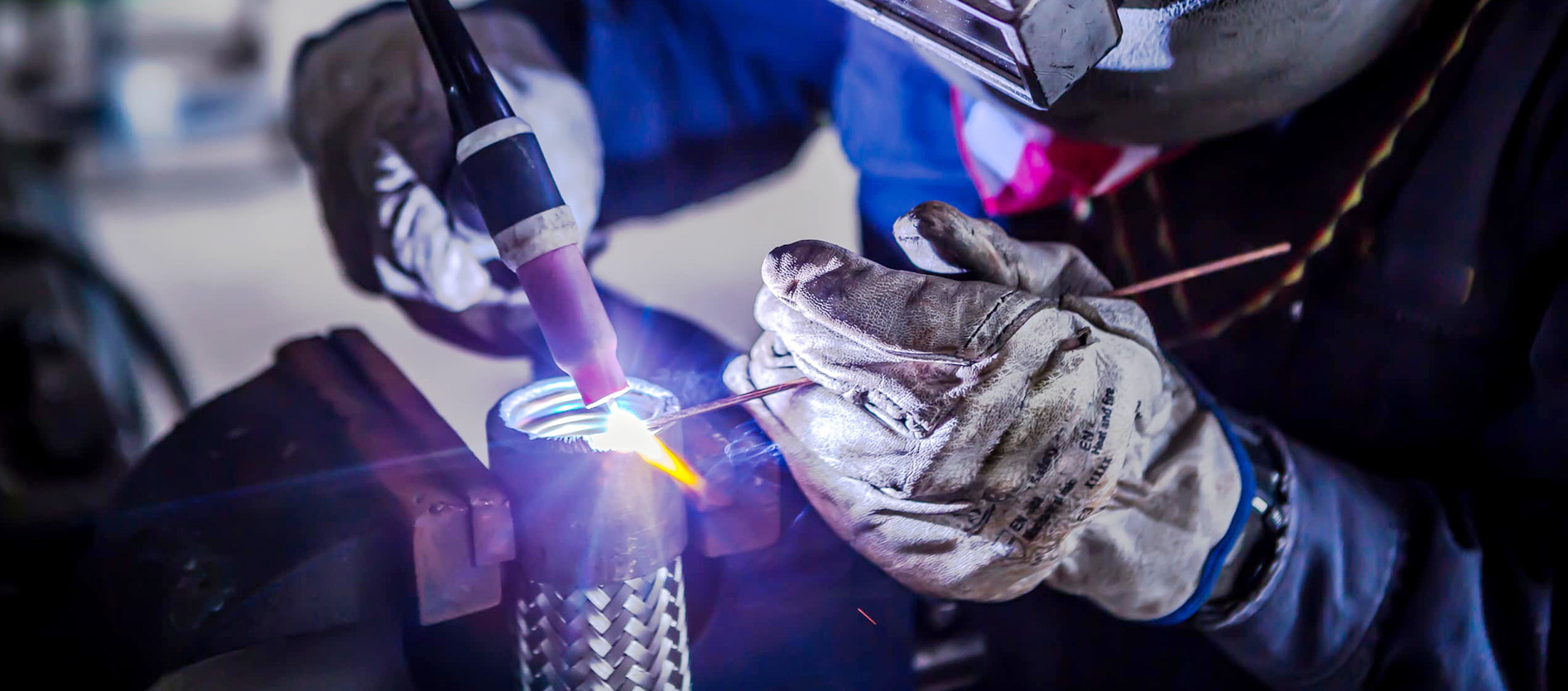
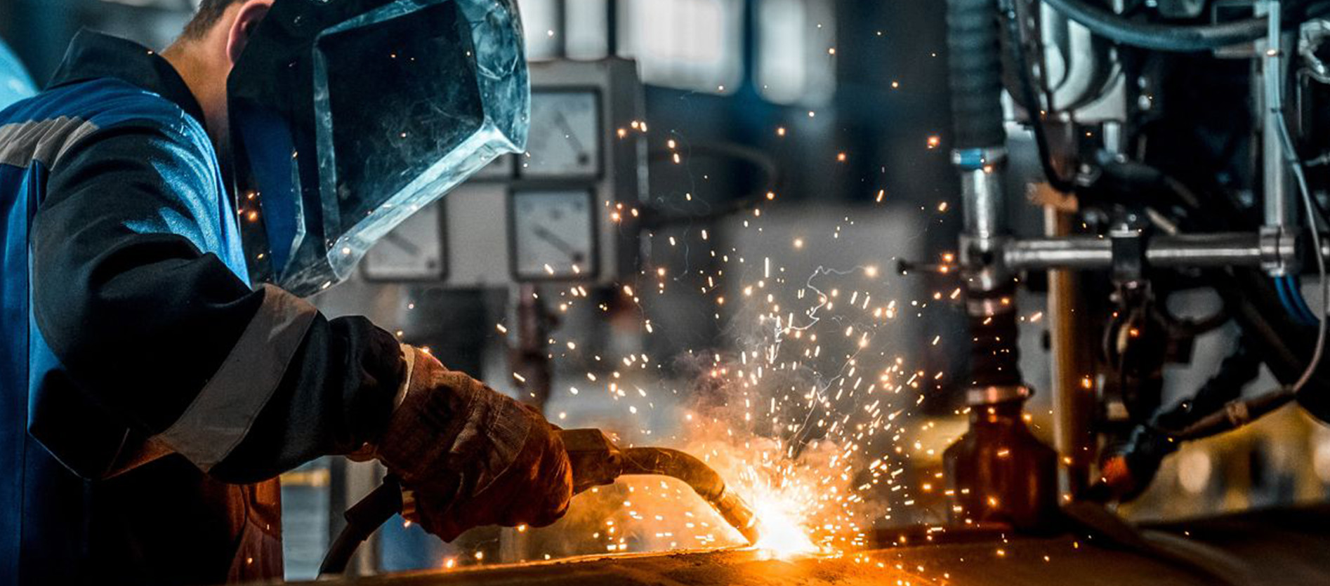
Agape has the capability to qualify the weld procedures to any nominatedstandard/s as per the customers requirement (BS EN ISO, ASME, AWS, AS etc).
We can qualify the welders at our facility to thestandards of ISO 9606 Parts, AWS, ASME etc.
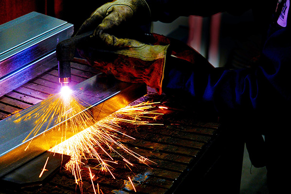
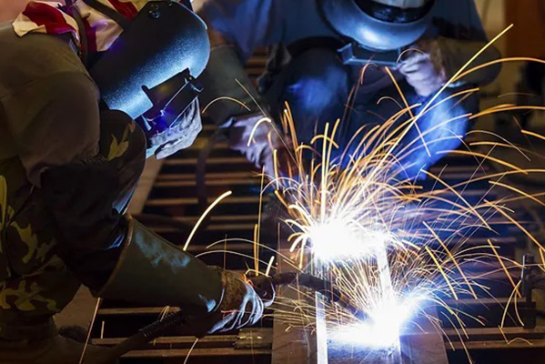
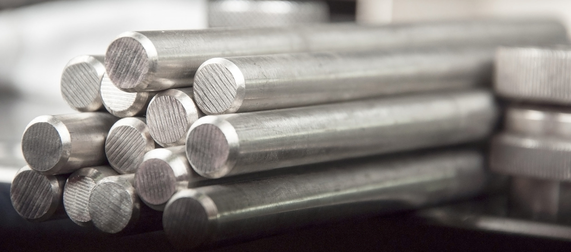
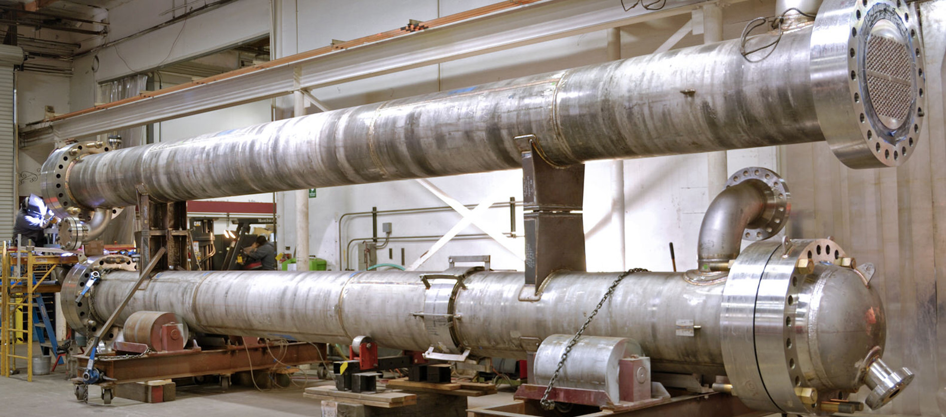
Our capabilityincludes fabrication of piping (stainless steel and other exotic materials) which demands high quality requirementand workmanship.
The materials, preferred processesare listed in the following sectionsthe additional treatment (post welding) to ASTM A380 can be organised by us (if specified under the executed contract) before handing over to the customer.
Type 304 is the general-purpose austenitic grade, widely used in applications requiring a good combination of corrosion and formability. Type 304L is a lower carbon modification of type 304 used in welding applications. The lower carbon content minimises carbide precipitation in the HAZ near welds, which can lead to intergranular corrosion in specific environments. Further modifications are types 304N and 304LN, to which Nitrogen is added.
Type 308 has higher chromium and Nickel contents than type 304 and is widely used as welding consumables. Type 309, 310 and 314 have higher nickel and chromium levels to provide oxidation resistance in high-temperature service. Type 309S and 310S are lower carbon versions used to minimise carbide precipitation near welds.
Type 316 contains Molybdenum and has a higher resistance to pitting corrosion in marine environments and chemical process streams than type 304. For type 316, variations include a Low-Carbon grade (316L), Nitrogen-containing grades for increased strength 316N and 316LN, and a higher Sulphur grade 316F for improved machinability.
Types 321 and 347 are stabilised with Titanium, Niobium and Tantalum, respectively, for applications requiring welding or for high-temperature services.
Why must care be taken for SS contact with low melting materials?
Care shall be taken during the fabrication process or welding to avoid contact with low melting point metals like Zinc (form of HDG or Zn-rich paints/primers) to avoid the issue of LME (liquid Metal Embrittlement).
Why is the Stainless steel welded surface to be cleaned, pickled or passivated post welding?
The heat tints are high-temperature oxides (Chemical Composition: consists mainly of Fe, Cr, Mn and Si, Thickness: Thicker than Passive Film, Structure: the scale is generally cracked and porous). These oxide scales destroy the passive film on the surface of the stainless steel) resulting inChromium depleted zone(non-self-passivation, and no corrosion resistance)
To ensure adequate corrosion resistance in the welded joint, the surface must be mechanically cleaned (wire brushing or Avesta TIG Brush) and all discolourisation removed. The client may specify additional cleaning requirements as per the ASTM A380 (by means of Pickling & Passivation) based on the use and the pitting potential.
What is the reason cross-contamination and cleanliness are critical for Stainless steel fabrication?
Oil, dirt and workshop dust can become sources of Carbon. SS have very low levels of Carbon to avoid sensitisation and thereby, corrosion issues.Tools shall be segregated from tools used for CS as Iron contamination creates initiation sites for corrosion.
Why shall special care be given to areas affected by Arc Strikes?
Arc Strikes occur in the joint itself as the material is remelted during welding. If the arc is initiated on the material away from the joint burn may form.These burns must be ground off without fail as corrosion may occur in these areas.
ASTM A790 UNS S31803, S32205 (Type 2205), S32750 (Type 2507) etc. materials over the Stainless Steel (ASTM A240) are selected 22% Cr Duplex & 25% Cr super Duples SS where high concentrations of Chlorides operating at temperatures up to 100& 140 Deg respectively.
Above these temperature ranges, CR alloy 625 were usually recommended by the engineers, for areas where the risk of SCC is anticipated.
Why is the control of the Thermal cycle is critical for DSS and SDSS during welding?
DSS and SDSS combine good resistance to SCC and high strength but are only suitable forservice down to -50 deg C. Both their toughness and corrosion resistance can be significantlyimpaired byexposure at temperatures within the range of 540 to 950 deg C because of the formationof a brittle sigma phase. The risk is minimised by tight control on thermal cycling during welding.
The brittle fracture that may occur in duplex and superduplex SS results from the formation of detrimental intermetallic phases, in particular, sigma phase (SDSS are more susceptible to sigma phase transformation during welding and extra care must be given during fabrication).
To avoid the detrimental phase transformation, the welding procedures shall be qualified and performed under strict quality control measures in order to ensure that the product meets the desired outcome.
Materials for Sour Service conform to NACE MR0175/ISO 15156 (usually referenced under the Client Specification)
Welding procedures for Titanium (ASTM B862) and other reactive materials (Mg, Tantalum, Zr etc) used in specialised applications for the chemical processing industry due to their exceptional corrosion resistance in a wide range of aggressive environments. Although most of these materials are considered weldable, their tendency to absorb Oxygen, Hydrogen and Nitrogen from the atmosphere encourages embrittlement restricted to specialised welding processes and procedures.The maximum tolerable limits in weld metal have been estimated as 0.3% oxygen, 0.15% nitrogen and 150ppm hydrogen so scrupulous cleanliness is essential for both parent metals and filler wires.
Ti has a very High Strength to weight ratio and Titanium has a strong affinity for oxygen and forms a dense, adherent oxide film on exposure to oxygen in the atmosphere. Ti oxides rapidly when heated in air to temperatures above 650 Deg C and must be protected from the atmosphere until it cooled to below 260 Deg C to avoid embrittlement caused by the absorption of Oxygen, Hydrogen and Nitrogen. Welding of Titanium, therefore, requires the use of additional protective shielding. Welding procedures for titanium and other reactive materials shall include provision forinternal and external continuous inert gas shielding until the metal temperature is lessthan the reactive temperature.
Contamination of the weld metal and the adjacent HAZs will increase tensile strength and hardness but may reduce ductility to an unacceptably low value such that cracks may occur even in conditions of only moderate restraint. The most likely contaminants are oxygen and nitrogen, picked up due to air entrained in the gas shield or from impure shield gas, and hydrogen from moisture or surface contamination.Solidification and liquation cracking are virtually unknown and what could perhaps be called cold cracking, occurs generally only because of embrittlement arising from contamination
Surface discolouration will give a good indication of the degree of atmospheric contamination as shown in the the colour chart (If not specified under the customer specification – Color chart can be referenced from AWS D1.9 Table 5.3 for Class C (Ballistically loaded structures)). Under perfect shielding conditions, the weld will be bright and silvery in appearance. Discolouration at the outer edges of the HAZ is not generally significant and may be ignored. As contamination increases, the colour changes from silver to a light straw colour, then dark straw, dark blue, light blue, grey and finally a powdery white.
The light and dark straw colours indicate light contamination that is normally acceptable. Dark blue indicates heavier contamination that may be acceptable depending on the service conditions. Light blue, grey and white indicate such a high level of contamination that they are regarded as unacceptable. In multi-pass welds the contamination will obviously affect any subsequent weld runs so that surface appearance alone is not a reliable guide to whether or not unacceptable contamination has occurred. A simple bend test is a reliable but destructive method of checking if the weld is unacceptably embrittled but note that the bend radius varies depending on the particular alloy.
Solid and Metal cored wires can be used in short-circuiting, globular and spray modes of arc operation to give a wide range of deposition rates and heat input levels. Solid and metal cored wires can therefore be used for a wide range of thicknesss.
Spray transfer mode is used to join sections thicker than about 6mm because deposition rates are higher than with other transfer modes.
For welding, 5%, 8% and 9% Nickel steel, the GMAW “Short-Circuiting” mode isusually not preferred/used. All Nickel Alloys shall be solvent cleaned and the interpass temperature shall not exceed 175 degrees C unless specified under the Client contract documentation.
Guidelines for Shielding Gas
- Shielding gas is generally Ar with 1 to 2% Oxygen added for Arc stability. Mixtures of Ar and He are employed if a hotter arc is desired.
- For 1G position, welding spray transfer is usually preferred.
- For other welding positions, the short-circuiting transfer is often used with Helium-rich gas such as 90% He-7.5% Ar-2.5% Carbon dioxide mixtures, or pulsed spray transfer can be employed using Ar or an Ar-He with a small addition of oxygen or Carbon dioxide.
- Super Duplex stainless would require Ar or Ar-He blended with 2% N2
- The highest purity shielding gas must be used. Ideally the gas should have a dew point of less than -50°C (39ppm H2O) and to maintain this low level the gas supply system should be free of leaks. Regular and frequent maintenance of the system is therefore essential, checking the joints for leaks and for damaged hoses.
For Titanium welding, a Leading shielding may also be required when a visual inspection or progressive-radius bend tests reveal excessive oxidation of the weld and surrounding base metal. The globular transfer is not recommended for welding Ti because of the high risk of excessive spatter and incomplete fusion. Spray transfer is recommended when welding thick sections in 1G and 2G positions. A longer, wider gas shield is required for spray transfer due to the high heat input. Pulsed spray transfer is advantageous for welding thinner sections and for welding in positions other than flat. The welding parameters used should always produce smoothly contoured welds that blend smoothly with the base metal.
Guidelines for Shielding Gas
The highest purity shielding gas must be used. Ideally the gas should have a dew point of less than -50°C (39ppm H2O) and to maintain this low level the gas supply system should be free of leaks. Regular and frequent maintenance of the system is therefore essential, checking the joints for leaks and for damaged hoses.
Manual GTAW process will be utalised. Material thickness upto 6mm DCEN is normally utalised.AC is sometimes usedto weld steels containing Al to take advantage of the arc cleaning action. The shielding gas is usually Ar, hut He or mixture of Ar-He are used for heavier sections. Argon-2% Nitrogen mixtures are sometimes used for super duplex stainless steels. All roots require shielding by trailing gas.
Torch nozzles should be fitted with gas lenses to improve gas shielding and the ceramic shroud should be as large a diameter as possible. A 1.5mm diameter tungsten, for example, should be used with a 16mm diameter ceramic. Arc lengths need to be as short as possible to reduce the risk of contamination; 1 to 1.5 times the electrode diameter is regarded as a good rule of thumb.
For Welding Titanium in open downhand position so that the weld tourch and secondary shielding devices maintain adequate inert gas shielding. To prevent porosity, specially designed secondary shielding devices should be used when welding out of position and the electrode extension beyond the gas nozzle should be limited to the amount required to ensure good weld pool visibility.. DCEN is normally used with Lathaniated, ceriated or thoriated tungsten electrodes.
Scratch starting should never be used to initiate the arc. The arc should be by the HF current or Lift Arc to prevent Tungsten inclusion. The welding tourch should dwell over the weld with a post-flow of shielding gas after interrupting the weld current. The post flow to be maintained until the weld cooled to below 260 Deg C. The head end of the filler etal should be held under the gas nozzle at all times to prevent contamination. A supplementary trailing gas shield will also need to be attached to the torch to provide protection to the cooling weld metal as the welder moves along the joint line. Several shields would therefore be required to weld a range of pipe diameters. A backing gas is also necessary and back purging should be maintained for at least the first three or four passes in a weld. Backing gas purity should be better than 20ppm maximum oxygen.
MIG welding using argon or argon/helium mixtures may be used but this process will not provide the same high-quality weld metal as the TIG process and it can be difficult to achieve the stringent quality levels required by aerospace applications. Dip transfer can lead to a lack of fusion defects, and spray transfer requires both leading and trailing supplementary gas shields, the leading gas shield to prevent oxidation of any spatter that may be remelted into the weld pool. The improvements in pulsed MIG power sources by using inverter technology and micro-processor control have obviated some of these problems and substantially narrowed the gap between MIG and TIG.
For any additional information please direct all your queries to engineers@agape.com.au